
Ringlock Scaffolding Blog
How to Erect Ringlock Scaffolding: A Practical Step-by-Step Guide
A practical Ringlock scaffolding erection guide covering layout, the first bay, standards, ledgers, bracing, alignment and U-head setup.
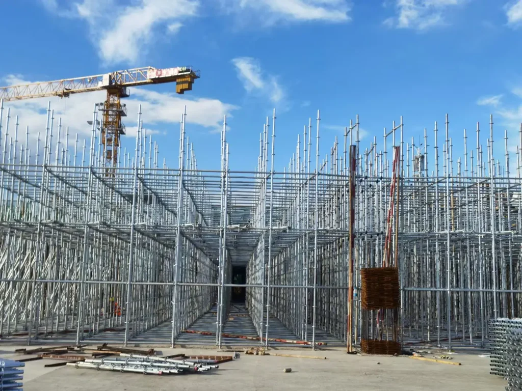
To erect Ringlock scaffolding: confirm the approved layout and Ringlock system, check the supporting surface, position the Base Jacks and Base Collars, establish and square the first bay, then install Standards, Ledgers and required Diagonal Braces progressively. Continue upward one level at a time while checking alignment and vertical connections, then install platform, access or U-Head components where required and complete the specified inspection before use.
Ringlock scaffolding erection is not simply a matter of connecting Standards, Ledgers and Diagonal Braces until the required height is reached.
The starting geometry matters. A poor base position, an out-of-square first bay or a connection that is forced into place can become a much larger problem several levels higher.
A practical erection sequence is:
Setting out → Supporting surface → Base setup → First bay → Standards and Ledgers → Diagonal Bracing → Vertical extension → Level-by-level checks → Platforms and access where required → U-Head arrangement for shoring → Final inspection.
The exact dimensions, bay arrangement, Jack extensions, bracing and scaffold height must follow the approved project layout, engineering design and applicable site requirements.
Table of Contents
- Before Erection Starts
- Set Out the Scaffold Grid
- Check the Supporting Surface
- Install Base Jacks and Base Collars
- Build the First Bay
- Install Standards and Ledgers
- Install Diagonal Bracing
- Extend Standards
- Check Each Level Before Continuing
- Platforms and Access
- U-Head Setup for Shoring
- Final Inspection
Before Ringlock Scaffolding Erection Starts
Before placing the first component, confirm what system and project information controls the erection.
Typical information includes:
- approved scaffold or shoring drawings;
- project configuration or BOQ;
- required Ringlock series;
- Standard lengths;
- Ledger sizes;
- Diagonal Brace arrangement;
- Base Jack and Base Collar requirements;
- top support arrangement where applicable;
- access and working-platform requirements.
Damaged, visibly deformed or incompatible components should be separated before erection begins.
If replacement components are being added to an existing inventory, do not assume compatibility from appearance alone. See Ringlock replacement component compatibility.
1. Set Out the Scaffold Grid
Start from the approved layout and mark the intended Standard positions.
Check bay dimensions and the relationship with walls, columns, openings, beams, equipment and other site restrictions.
Do not casually move one Standard because the planned position is inconvenient.
A change at ground level can affect:
- adjacent bay geometry;
- Brace fit;
- support positions;
- access;
- the load path through the scaffold.
Site CheckIf one position needs to change, check what that change does to the rest of the approved arrangement before continuing.
2. Check the Supporting Surface
The scaffold ultimately transfers load through its lower components into the supporting surface.
Before installing the bases, check for obvious soft areas, water accumulation, poor drainage, major level differences or areas disturbed by excavation and other site activity.
Loose bricks, steel offcuts or unrelated materials should not be used simply to compensate for an unsuitable support condition.
For the detailed inspection process, see scaffold ground and base support inspection.
3. Install Base Jacks and Base Collars
Position the Adjustable Base Jacks and install the required Base Collars.
At this stage, check:
- full support below the base plate;
- screw straightness;
- thread condition;
- normal nut movement;
- Base Collar fit;
- reasonable initial adjustment.
A Base Jack provides controlled adjustment. It should not be used to hide a poor supporting surface or a major height error.
Total Jack length is not the same thing as permitted working extension.
4. Build and Check the First Bay
Connect the first Ledgers and establish the starting bay before building upward.
Check the bay dimensions, level, Standard positions, base seating, Ledger-head seating and wedge engagement.
If the first bay is visibly out of level or square, correct it now.
The first bay acts as the geometric reference for everything above it. Small errors here can become much more obvious after several lifts.
For the detailed procedure, see how to level and square the first bay of Ringlock scaffolding.
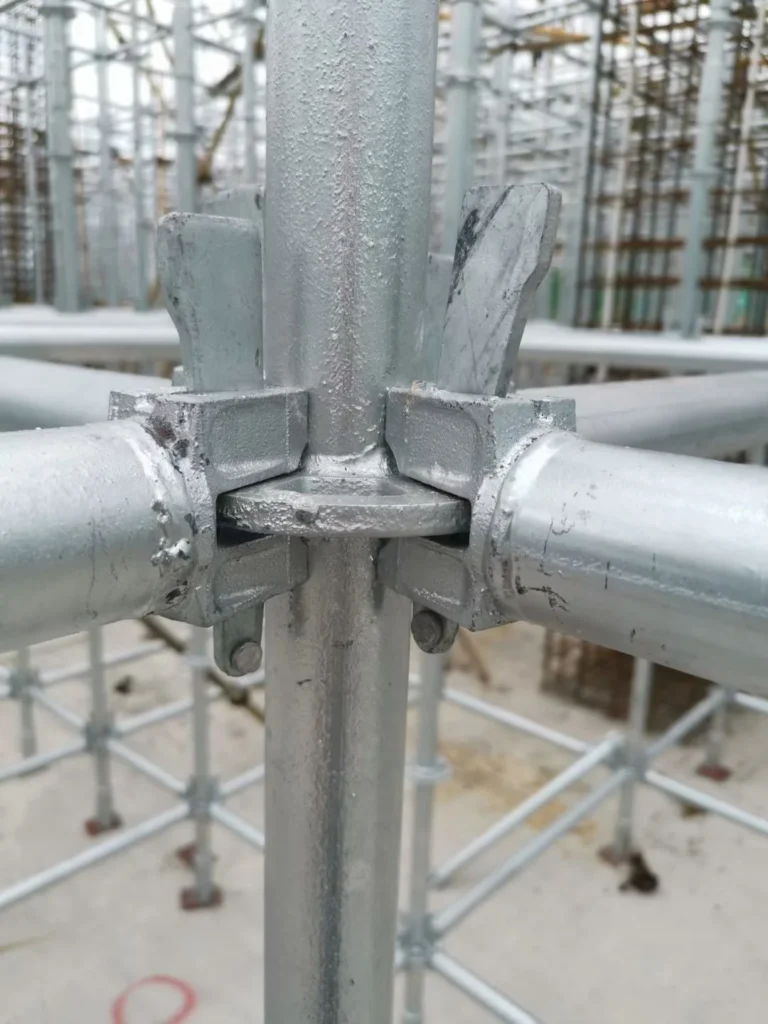
5. Install Standards and Ledgers
Once the starting bay is correct, continue with the required Standards and Ledgers.
Check that:
- the correct component sizes are being used;
- Standards are properly seated;
- Ledger heads sit correctly at the rosettes;
- wedges engage normally;
- the bay geometry remains consistent.
A wedge passing through the rosette does not by itself prove that the complete connection is correct.
If a connection remains abnormally loose, inspect the complete node rather than using more force.
6. Install Diagonal Braces as the Scaffold Develops
Required Diagonal Braces should develop with the scaffold according to the approved arrangement.
They should not automatically be left until the full height has already been erected.
If a Brace does not fit its intended nodes naturally, check the bay geometry, Standard alignment, Brace size and component compatibility before forcing the connection.
A required Brace should not simply be removed because it is difficult to install.
For the specialist guide, see when Diagonal Braces should be installed in Ringlock scaffolding.
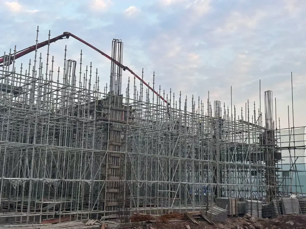
7. Extend Standards Correctly
When more height is required, extend the Standards using the connection arrangement specified for the actual Ringlock system.
Depending on the product, the vertical connection may use a sleeve, connecting spigot or another confirmed arrangement.
Check the upper Standard, connection type, seating, alignment, sleeve or spigot condition, rosette orientation and whether foreign material is preventing normal connection.
For the dedicated procedure, see how to extend Ringlock Standards and check vertical connections.
8. Check Each Level Before Continuing
Do not erect several levels first and plan to correct all geometry at the top.
A useful erection rhythm is:
Install → Check → Correct → Continue.
Warning signs that something has already started drifting include:
- Standards gradually leaning;
- Ledgers becoming harder to install;
- Braces no longer reaching their intended nodes;
- repeated use of excessive force;
- the scaffold grid moving away from the approved arrangement.
A useful field principle is: Build one level, check one level.
For troubleshooting, see why Ringlock scaffolding goes out of alignment during erection.
9. Install Platforms and Access Where Required
Where the structure is being used for access or working platforms, install the specified components according to the approved arrangement.
These may include:
- Steel Scaffold Planks;
- Staircases;
- access platforms;
- Side Brackets;
- guardrail components;
- other approved accessories.
Working platforms should not be improvised from unrelated materials simply because they happen to span between two supporting members.
For the dedicated safety guide, see scaffold working platform and access safety checklist.
10. Install U-Head Jacks for Shoring Applications
For concrete shoring or falsework applications, Adjustable U-Head Jacks may be installed at the top of the Ringlock support.
Check screw condition, thread and nut operation, plate condition, adjustment and seating of the supported beam.
The U-Head should provide controlled final adjustment.
It should not become a way to compensate for a support structure below that was erected at the wrong height or geometry.
Product length is not the same thing as permitted working extension.
See Ringlock Base Jack and U-Head Jack inspection for the specialist inspection.
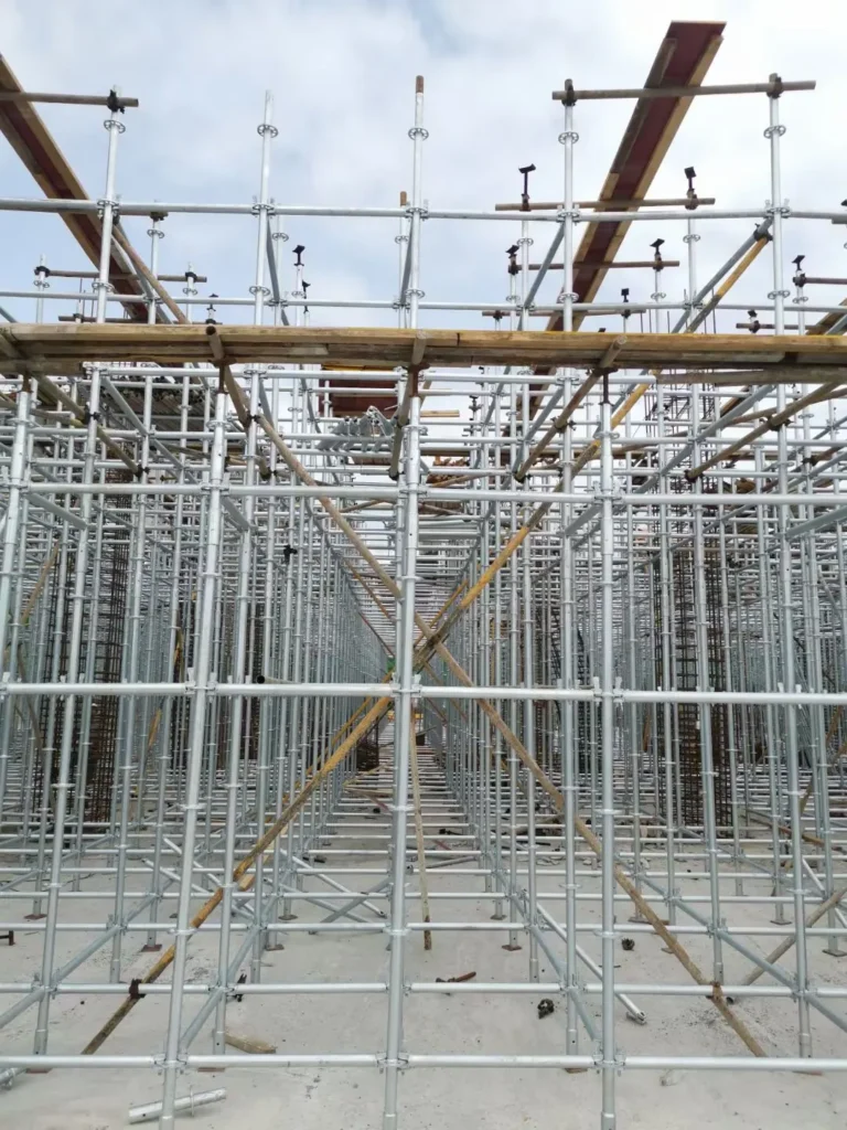
11. Check the Complete Structure Before Use
Before the scaffold or shoring structure is placed into service, complete the inspection required by the project procedure.
| Check Point | What to Look For |
|---|---|
| Supporting Surface | No obvious instability or loss of support |
| Base Components | Base plates seated and adjustment condition acceptable |
| Scaffold Grid | Still follows the approved arrangement |
| Standards | Proper seating and no obvious abnormal alignment |
| Ledgers / Wedges | Ledger heads seated and connections engaged |
| Diagonal Braces | Required Braces installed in intended positions |
| Vertical Connections | Standard joints fully seated and aligned |
| Platforms / Access | Installed as required for the intended use |
| U-Heads | Proper adjustment and beam seating where used |
| Component Condition | No obvious serious damage at critical components or connections |
This is an erection-stage check. It does not replace the detailed product inspection process.
For the broader component inspection, see Ringlock scaffolding inspection checklist.
Common Erection Problems Should Be Corrected Where They Start
If a Ledger becomes difficult to install, do not assume the Ledger is the problem.
If a Brace stops fitting, check the geometry around it.
If the upper Standards start leaning, inspect the level below.
If a U-Head needs unusually large adjustment, check the height and geometry underneath it.
The erection control principle can be summarized as:
Install → check → correct → continue.
For a problem-based guide, see common Ringlock scaffolding erection mistakes.
There Is No Universal Ringlock Erection Spacing
This guide intentionally does not provide one universal:
- Standard spacing;
- Ledger spacing;
- Diagonal Brace arrangement;
- Base Jack extension;
- U-Head extension;
- maximum scaffold height.
Those values depend on the actual application, project geometry, loads, Ringlock configuration, support height, formwork arrangement and approved engineering design.
Ringlock Supply and Scaffold Engineering Are Different Responsibilities
A Ringlock supplier can prepare components according to confirmed specifications, drawings and BOQs.
TJJG can support product specification confirmation and quantity review based on customer-provided information.
The final determination of spacing, bracing, support height, Jack extension and structural capacity belongs to the project engineering process.
FAQ
Frequently Asked Questions
Quick answers to common Ringlock erection questions.
What is the basic sequence for erecting Ringlock scaffolding?
Start with the approved layout and supporting surface, position the Base Jacks and Base Collars, establish the first bay, install Standards and Ledgers, add required Diagonal Braces progressively, extend Standards level by level and complete the specified platform, top-support and final inspection work.
When should Diagonal Braces be installed?
Required Braces should normally be installed progressively as the scaffold develops according to the approved arrangement rather than automatically being left until final height.
What should be checked when extending Ringlock Standards?
Confirm the correct upper Standard and vertical connection type, then check the sleeve or spigot, full seating, alignment, rosette orientation and whether anything prevents normal connection.
Can Adjustable Jacks correct a badly erected scaffold?
They are intended for controlled adjustment. Major ground, height or geometry problems should be corrected at their actual source rather than hidden through excessive Jack adjustment.
Conclusion
Good Ringlock erection is not just about following a list of components.
Set out the grid, establish suitable support at the bottom, build the first bay correctly, add Standards, Ledgers and required Braces progressively, extend vertical connections carefully and check each level before continuing.
If a problem appears, correct it where it starts.
The most useful erection sequence is not:
Install → install → install.
It is:
Install → check → correct → continue.
Discuss Your Ringlock Requirement
If you are preparing a Ringlock scaffolding or shoring requirement, send the component list, required series, quantities, destination or available drawings. We can review the supply requirement and product information with you.
Product Center
Related Products