Common Ringlock Scaffolding Erection Mistakes
Most Ringlock erection problems are not caused by the last component that becomes difficult to install. A Ledger, Brace or Standard that does not fit correctly is often showing an earlier problem in layout, alignment or component selection.
In practical erection work, the final connection where a problem becomes visible is usually not where the problem started. A fitting issue at an upper level may have developed from a smaller error in the first bay, base support condition or component selection several steps earlier.
This guide focuses on troubleshooting common Ringlock scaffolding erection mistakes. It is intended to be used together with the approved erection procedure and project requirements, not as a replacement for the correct assembly sequence.
For the complete installation process, see How to Erect Ringlock Scaffolding.
Start with the Symptom, Then Trace Back to the First Error
If a Ledger becomes difficult to install, a Brace no longer reaches its intended node, or Standards begin to lean, the most useful approach is not to force the connection or continue building upward.
Treat the visible problem as a warning signal. Find the earliest point where the scaffold stopped following the intended geometry, then correct that condition before continuing.
| Observed problem | Check first | Detailed guide |
|---|---|---|
| Ledgers become harder to install as the scaffold height increases | First-bay geometry, lower-level alignment and connection seating | Alignment troubleshooting |
| One base is no longer fully seated | Ground condition, base support and first-level adjustment | Ground and base support |
| Brace does not reach the intended node naturally | Bay geometry, Standard alignment and correct Brace selection | Diagonal Brace timing |
| Upper Standard connection appears offset | Vertical joint seating, alignment and connection condition | Standard vertical connections |
| Multiple components require excessive force during assembly | Geometry, component condition, damage or system compatibility | Component compatibility |
| U-Head position moves away from the intended support line | Accumulated alignment error below the support point | U-Head beam seating |
Mistake 1: Moving Standards on Site to Avoid an Obstruction
One common field problem occurs when a Standard is moved temporarily to avoid an obstruction such as a wall, opening, pipe, column or equipment foundation.
Although the adjustment may appear small, changing one Standard position can affect adjacent bay dimensions, Ledger lengths, Brace locations and the final support position.
If the approved arrangement no longer fits the actual site condition, the change should be reviewed before continuing erection. A temporary adjustment made during installation can create a larger geometry problem several levels above.
Mistake 2: Carrying a First-Bay Error Upward
The first bay establishes the starting geometry of the scaffold. If the initial unit is not level and square, later levels usually inherit the same error.
A common mistake is trying to correct a starting error after several levels have already been erected. At that stage, the visible problem may appear at a Ledger connection or upper Standard joint, but the original cause is lower down.
Correct the first unit before continuing upward. The detailed setup process belongs to first-bay leveling and squaring.
Mistake 3: Using Jack Adjustment to Hide a Ground Support Problem
Base Jacks provide controlled adjustment, but they cannot turn an unsuitable supporting surface into a stable foundation condition.
Poor seating, settlement, water damage, loose packing materials or significant level differences should be corrected at the support condition itself rather than hidden by excessive adjustment.
When unusual Jack extension becomes necessary, the first question should be whether the base condition is correct, not whether more adjustment is available.
Mistake 4: Forcing a Connection Instead of Investigating the Cause
A connection that requires excessive force is usually a sign that something earlier needs to be checked.
More hammer force does not solve a geometry problem. If a Ledger, Brace or Standard repeatedly refuses to reach its intended position, inspect:
- bay geometry;
- component condition;
- connection area;
- system compatibility.
From a component supplier’s perspective, a connection that can only be achieved by force should be treated as a warning sign, not as a successful installation.
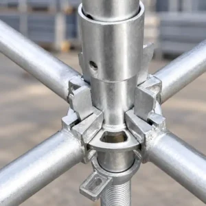
For loose Ledger nodes, inspect the complete rosette, wedge and Ledger head connection rather than focusing only on the wedge itself. See Ringlock rosette, wedge and Ledger connection inspection.
Mistake 5: Installing Required Diagonal Braces Too Late
Where the approved arrangement requires diagonal bracing, the Brace is part of the erection process, not a finishing component added after the scaffold is already complete.
Delaying required Braces allows the structure to continue growing while the original geometry is less controlled. Once several levels have been added, correcting the resulting movement becomes more difficult.
Adding another Standard does not replace the function of a required Diagonal Brace. Each component has its intended role in maintaining the designed arrangement.
Mistake 6: Ignoring the Last Vertical Standard Joint
A scaffold can begin correctly and still develop problems after several levels of erection if a Standard-to-Standard connection is not fully seated or correctly aligned.
When an upper level suddenly becomes difficult to assemble, do not only check the component that no longer fits. Inspect the most recent vertical joint for full seating, alignment, connection condition and correct component selection.
A small error at a vertical connection can influence the geometry of the structure above it.
Mistake 7: Mixing Ringlock Components by Appearance
Two components can both be sold as Ringlock parts and still differ in series, connection geometry, dimensions or manufacturing details.
Visual similarity alone does not prove compatibility. A replacement component should be identified by the actual system, dimensions, connection details and physical fit.
This is especially important when replacing used or damaged components. A part that appears similar may still create problems during erection if the connection geometry does not match.
Mistake 8: Using Adjustable Jacks to Correct an Accumulated Geometry Error
Base Jacks and U-Heads are adjustment components. They are not intended to pull a badly aligned scaffold back into position.
If unusually large adjustment is required, check the conditions below first:
- starting elevation;
- base support condition;
- component selection;
- overall scaffold geometry.
Large adjustments often indicate that an earlier condition needs correction rather than additional adjustment.
Mistake 9: Continuing After the Scaffold Has Started Showing Warning Signs
A scaffold usually provides several signs before a serious assembly problem develops.
Examples include:
- progressive leaning;
- multiple Ledgers requiring force;
- Braces missing their intended nodes;
- bases losing proper seating;
- the scaffold grid moving away from the approved arrangement.
When several warning signs appear together, stop and trace the cause instead of continuing upward.
A simple site rule is:
Do not carry a known problem into the next level.
Mistake 10: Changing the Scaffold After Acceptance Without Re-Inspection
A scaffold can be correct when inspected and later become different from the accepted condition.
Removing a Ledger, Brace, platform component or another structural part for temporary access changes the erected arrangement.
Any modification should follow the project control procedure and require re-inspection before the scaffold returns to service.
What This Page Does Not Define
This guide does not create universal values for Standard spacing, Ledger spacing, alignment tolerance, Brace spacing, Base Jack extension or U-Head extension.
Those values depend on the actual Ringlock system, approved project arrangement, engineering requirements and applicable regulations.
The purpose of this article is troubleshooting logic: identifying where an erection condition changed and correcting the cause before the problem becomes larger.
Use Erection Mistakes as Diagnostic Clues
The most useful way to understand an erection mistake is to ask what later symptom it can create.
| Early Mistake | Typical Later Symptom |
|---|---|
| Base positions do not follow the approved set-out | Bay dimensions drift and later Ledgers or Braces become difficult to fit. |
| The first unit is locked before it is leveled and squared | Errors are carried upward and become harder to correct at higher levels. |
| Required Braces are delayed | The starting geometry becomes easier to disturb while additional bays are added. |
| A connection is forced instead of inspected | The actual source of the fit problem remains hidden and may appear again at another node. |
| Several levels are erected before alignment is checked | Small errors accumulate into visible leaning or repeated fitting problems. |
A Better Control Rhythm
A practical erection rhythm is not:
Erect as much as possible, then inspect.
A more reliable approach is:
Set out → form a stable unit → level and square → brace as required → lock → check → continue.
The exact erection details still follow the approved method and system requirements. The purpose of this sequence is to remove errors at the stage where they are easiest to identify and correct.
Conclusion
Common Ringlock erection mistakes are best handled as a troubleshooting problem.
Identify the symptom, trace the geometry back to the earliest incorrect condition, and correct the cause before continuing.
The component that refuses to fit is often only showing where an earlier problem finally became visible.